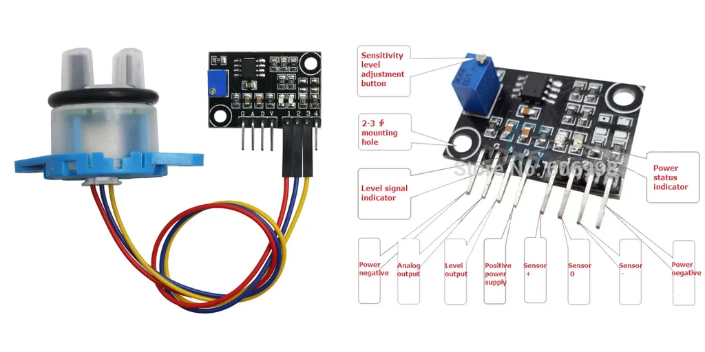
Датчик мутности: Turbidity Sensor Suspended Turbidity Value Detection Module Kit
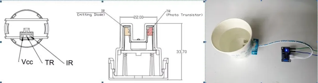
Датчик китайский, говорят — хуевый, сильно зависит от освещения. Кроме того, я не представляю как он может обеспечивать герметичность, он вообще ни хрена ни герметичный, там светодиод с фотодатчиком и пластиковый колпачок, который надевается и предполагается, что в щели вода не пройдет и плату не зальет. Я бы залил там как минимум, герметиком.
V — VCC 5V (не 3.3V!) A — analog signal output 0...4.5V (вешаем резисторный делитель) D — digital signal output (не используем) G — GND
1 (VCC) — «Sensor +» — красный 2 — «Sensor 0» — TR — синий 3 — «Sensor -» — IR — желтый 4 (GND) — не используется
Осторожно! В интернете встечаются фотки от долбоебов, которые подключили сенсор к пинам G A D и сфоткали так для своего магазина, не понимая, что это.
Для калибровки надо поместить датчик примерно в условия использования, взять стандартный калибровочный раствор 0NTU (или дистиллированную воду) и измерить температуру T0 и напряжение V0 на калибровочном растворе. Далее вычислять TU по формуле:
TU = -865.68 * V + (865,68 * (V0 — (-0.0192 * (T0-25) ) ) )
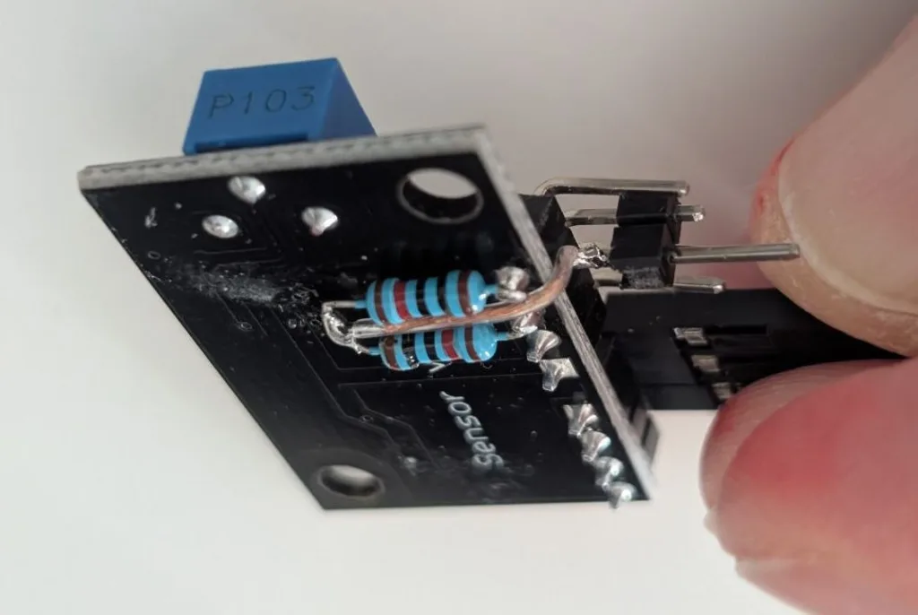
Подключение. Поскольку устройство 5 вольт, выход у него аналоговый тоже 5 вольт. А в чипе ESP максимум измерения 3.3 (включается analogSetAttenuation 32 3.3), не сжечь бы еще. Поэтому делаем мост: берем два резистора по 10 килоом и включаем их последовательно между А и G. А сигнал берем с их середины, где они соединяются. Я сделал так:
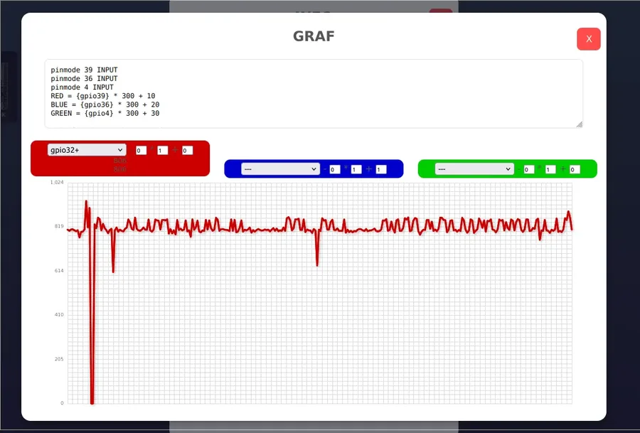
Подключать лучше к пинам, помеченным "+" в плагине графиков — обычно это пины из третего десятка:
В консоли предварительно лучше сказать (допустим, номер пина 32):
Графики я немного еще починил, не зависают теперь при повторном запуске.
всякая херня
Description report
Product introduction:
The turbidity of water refers to the degree of turbidity caused by suspended substances such as silt, clay, organic matter, plankton and microorganisms contained in the water. Industrial-grade turbidity sensors or turbidity meters are expensive, and the cost is too high in the design of electronic products. Therefore, we have selected a turbidity sensor that is widely used in household appliances, washing machines, and dishwashers. The sensor uses optical principles to comprehensively judge the turbidity through the light transmittance and scattering rate in the solution. Inside the sensor is an infrared tube. When light passes through a certain amount of water, the amount of light transmission
depends on the degree of dirtiness of the water. The dirtier the water, the less light it transmits. Light
The receiving end converts the intensity of the transmitted light to the corresponding current size. The transmitted light is more and the current is larger. On the contrary, the transmitted light is less and the current is smaller.
The turbidity sensor module converts the current signal output by the sensor into a voltage signal, and performs AD conversion data processing through the single-chip microcomputer. The remodeling module has analog and digital output interfaces. The analog quantity can be sampled and processed by the single chip A/D converter to know the current water pollution. The digital value can be adjusted through the potentiometer on the module to adjust the trigger threshold. When the turbidity reaches the set threshold, the D1 indicator will be lit, the output of the sensor module changes from high level to low level, and the single chip monitors the change in level To determine whether the turbidity of the water exceeds the standard, so as to warn or link other equipment. The module is inexpensive, easy to use, and has high measurement accuracy
It can be used to measure the degree of water pollution of products such as washing machines and dishwashers; it can also be used in industrial field control, environmental sewage collection and other occasions that require turbidity detection and control.
Module introduction and pin definition:
The composition of the turbidity sensor module is shown below. The module is connected to the turbidity sensor through the 3Pin XH-2.54 connector. Adjust the knob of 10K blue potentiometer to adjust the trigger threshold of digital output.
The module pin definitions are as follows:
1 VCC: Positive supply voltage, 5V cannot be used 3.3V
2 AO: analog signal output, output voltage range 0~5V
3 DO: digital signal output is less than the set value and outputs high level; greater than the set value and outputs low level
4 GND: negative supply voltage
Technical index:
Working voltage: 5.00V DC Working current: 40mA (MAX) Response time: <500ms Insulation resistance: 100MΩ (Min) output method:
Analog output: 0~4.5V; Digital output: high/low level signal (the corresponding threshold can be selected by adjusting the potentiometer) Operating temperature: -20℃~90℃ Module size: 38.6mm*22.1mm
Introduction of supporting turbidity sensor:
The turbidity sensor model of this sensor module is TSW-30, as shown in the following figure.
Приведенная выше формула представляет собой разность напряжений, вызванную изменением температуры; T — текущее измеренное значение температуры.
(4) Метод калибровки
Из-за индивидуальных различий в датчиках мутности, окружающего освещения или отсутствия температурной компенсации. Для получения более точных результатов
Перед измерением необходимо откалибровать точное значение мутности. Конкретный метод работы описан ниже.
Шаг 1: Установить датчик мутности, подключить к модулю датчика. Для калибровки использовать стандартный раствор 0NTU (или дистиллированную воду, близкую к 0NTU).
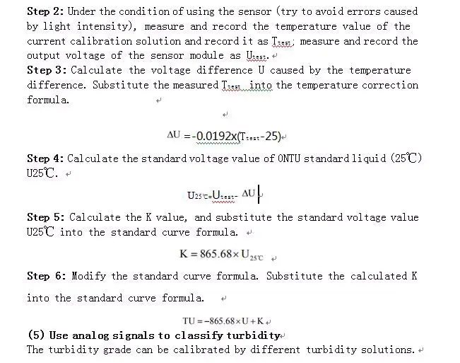
Шаг 2: В условиях использования датчика (стараясь избегать ошибок, вызванных интенсивностью света) измерить и записать:
Шаг 3: Вычислить разность напряжений dU, вызванную разностью температур, подставив Ttest в формулу температурной поправки:
dU = -0.0192 * ( Ttest — 25 )
Шаг 4: Вычислить U25c — стандартное напряжение на стандартной жидкости 0NTU при температуре 25°С (U25°C).
U25с = Utest — dU
Шаг 5: Рассчитать значение K и подставьте значение стандартного напряжения U25с в формулу стандартной кривой.
K = 865,68 * U25с
Шаг 6: Измените формулу стандартной кривой. Подставьте рассчитанное значение K в формулу стандартной кривой:
TU = -865.68 * U + K
(5) Используйте аналоговые сигналы для классификации мутности. Степень мутности можно откалибровать с помощью различных растворов, обладающих разной степенью мутности.